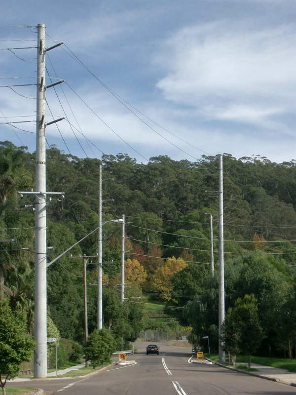
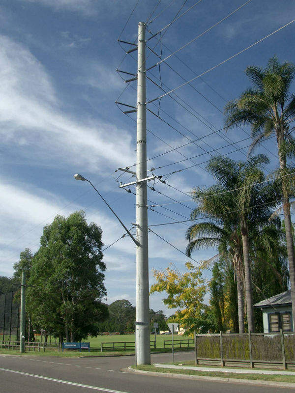
Rob Wilks is the author of Livewire 3 and is now supporting and marketing the software. He has more than 33 years experience surveying and designing pole type power lines from distribution to multi-circuit 132kV sub-transmission lines on concrete poles. His aim was to create a power line design tool that was both comprehensive and easy-to-use.
Some benefits of using the software are:
- Hassle free quality power line designs
- Huge cost savings in power line design time
- Design staff satisfaction
- Optimised designs for different scenarios
- ‘Field to Finish’, no extra modules required
- Especially suitable for power line upgrades
- Automatic processes aid quality assurance
Livewire software for design and construction of overhead power lines
The relatively new Australian and New Zealand standard (AS/NZS 7000:2010) for the design and construction of overhead power lines is ‘limit state design’ oriented and will make it imperative that power line design and construction companies comply with this standard. It would be convenient if a design tool existed that was based on the new standard and facilitated its application to new power line designs.
Such a design tool in the form of a computer programme called Livewire 3 is now available.
It is an Australian product that simplifies the application of ‘Limit State’ principles when applied to power line designs. It also makes it easy to enter recommended limit state design parameters from the standard into the programme.
Computer programme tool for civil and mechanical design of pole-type power lines
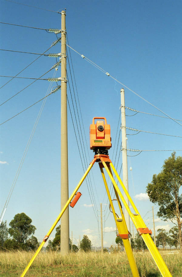
Livewire 3 is a ‘field to finish’ product. Electronic survey data from electronic total stations or global positioning system (GPS) survey equipment can be downloaded into the programme. The design is then completed and the relevant CAD drawing files produced are ready to include in the final construction drawing, facilitating high-quality and rapid throughput designs.
Design flexibility of transmission power lines
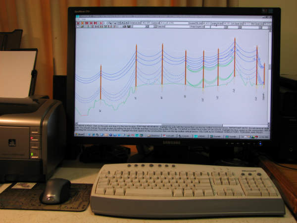
Survey data can be entered in several different ways and processed to obtain the ground profile. Poles, constructions and conductors are then added to the ground profile by choosing them from their respective dropdown menus on the interactive design screen.
Once the components have been added, it is then a simple matter of selecting different pole heights, changing conductor tensions and manipulating the poles and cross arms with the mouse so that adequate circuit to circuit and ground clearances are achieved. These components can be manipulated interactively in real time from the one screen.
Automatic load and clearance checks for the design of power line structures
Now that the conductor clearances are adequate, the click of a button initiates automatic load and clearance checks for pole, foundation, cross-arm and insulator strengths, as well as mid-span separation and conductor uplift calculations. For situations where a strong enough pole is not available, optimum stay strengths and stay positions can be visually determined. When the designer is satisfied with the design, DXF CAD files can be easily created for the route plan, profile, construction schedule and stringing tables.
Some special features of Livewire 3 are:
- The speed at which the load and clearance calculations are carried out
- The visual indication of where any design violations occur for instant recognition
- The graphical analysis feature which allows the designer to visually optimize pole, footing and stay strengths, as well as stay locations, thus simplifying a complicated process

