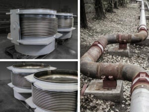
Belman’s Bespoke Pressure-Balanced Expansion Joints
Many applications have design constraints that require a unique expansion joint design. This causes problems if the exact expansion joint type takes up more space than the arrangement of the pipeline permits.
This conflict was resolved for an Austrian Biomass plant through the customised pressure-balanced expansion joint with a hidden balance chamber.
Remarkable solution
The Austrian biomass plant required an expansion joint to be located in the turbine steam pipe.
In a turbine system, there are usually defined limits regarding the permissible sizes of forces and/or movements transmitted to the turbine flange. These forces/movements originate from the rigidity of the expansion joint and the operating pressure in the pipeline. In this case, the permissible sizes of forces/movements were so tightly restricted that it was necessary to install a pressure-balanced expansion joint with a low spring rate. This eliminated the pressure reaction force and the majority of forces acting on the turbine flange, while the residual forces/movements were minimised due to the low spring rate. In addition to these criteria, the pipeline layout meant that the built-in length of the expansion joint had to be kept to a minimum. This resulted in an alternative pressure-balanced construction with the balance chamber placed between two bellows.
Hidden balance chamber
Normally, an inline pressure-balanced expansion joint consists of a large balance bellow with a flow bellow positioned at either side.
The balance bellow has an effective area exactly twice the area of each flow bellows, while mechanical connections across the bellows contain the pressure force.
By using an arrangement where one flow bellow is placed inside the balance bellow, it is often possible to achieve a space saving of approximately one-third in comparison with the conventional simple unit. A further advantage of this arrangement is that it usually leaves space for longer bellow elements with more convolutions while providing less stiffness and minimising deflection forces.
Pressure equalisation is achieved by providing the medium access to the balance chamber, which has an effective area equal to that of the flow bellows, and using mechanical restraints to contain the pressure force whilst allowing deflection.
Drainable solution
A commonly requested feature of pressure-balanced expansion joints is the provision of a drainage connection for the balance chamber. This is a simple connection with a plug located at the position of the lowest point of the chamber where the expansion joint is installed.
The drain is closed and sealed with the plug when the unit is in service but can be opened to allow drainage when the operation is shut down or interrupted for routine maintenance.
The advantage of pressure-balanced expansion joints
Pressure-balanced expansion joints have the advantage that it is possible to remove reaction forces, which would otherwise be transmitted to the pipe system, internally in the expansion joint.
This can be advisable as the installation of a conventional expansion joint often releases great forces in a pipe system. This makes demands on supports and guides as these have to be dimensioned accordingly.
It can often be financially beneficial to use pressure-balanced expansion joints in a pipeline, as supports and guides in certain cases can be dimensioned significantly smaller than in a conventional solution. However, it should be noted that there are other possible solutions for eliminating reaction forces in the pipeline, for example, by designing the piping so that movement is absorbed in lateral and/or angular expansion joints. In certain situations, if the space is very limited, such pipe system layouts are not possible and, in these cases, pressure-balanced expansion joints are often used.
Design parameters
Dimension: DN 800
Installation length: 1100 mm
Medium: Steam
Design pressure: -0,55/2 barg
Design temperature: -300°C
AX: +0/-39 mm
LA: +13/-0 mm
Bellow: 1.4541
Flanges and welding ends: 1.0425
Inner sleeve: 1.4541


