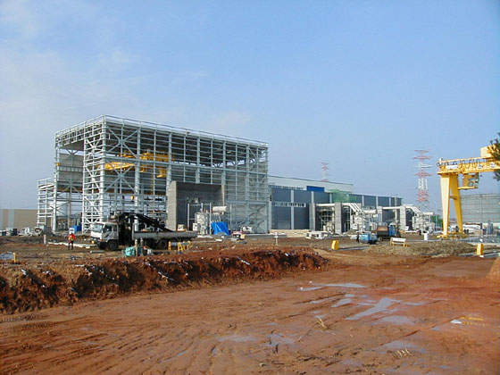
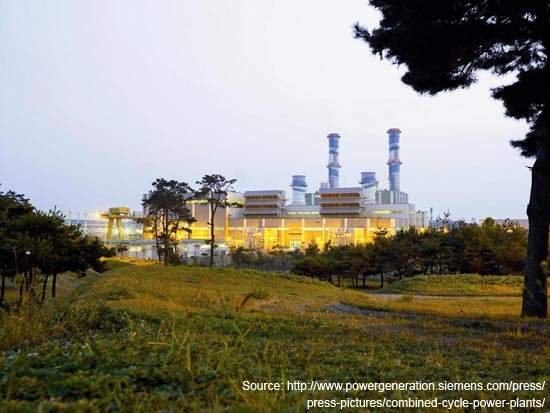
Bugok CCGT Power Plant is an LNG combined cycle power plant located at Bugok Industrial Complex in South Korea. It is located at Dangjin-gun, Province of Chungchong Nam-do, approximately 120km south of Seoul.
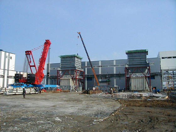
The project involved the construction of two power plants in two different phases. The first power plant Bugok I, with 550MW generating capacity, started operating in 2001. The construction of Bugok II, the second phase of the power plant with a capacity of 550MW, began in November 2005 and was completed in March 2008.
The plant is owned by the LG Energy Company (LG Energy), a new subsidiary of LG Corporation (formerly Lucky Goldstar). LG was the only one of ten local developers to be permitted to build such a plant (the permitting authority was Korea Electric Power Company or KEPCO). LG Energy was responsible to design the Bugok project. The Bugok site was chosen because it was easy to connect to the grid, as well as being close to a major gas pipeline.
The plant is currently operated by GS EPS Co Ltd (GS EPS), which is 70% owned by GS Holdings and 30% by Oman Oil Co. GS Holdings took over LG Energy Co, which was in turn founded by LG Corp to develop Bugok.
GS EPS is South Korea’s first independent power producer, with the country having earlier liberalised its markets to allow this.
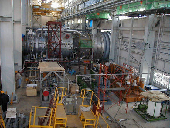
The power plant was built on land reclaimed in early 1998. The original contract for turbines was signed in 1997. The two V84.3A gas turbines and one steam turbine were installed in March 2001 and handed over to the private plant operator, LG Energy Co.
Bugok II doubles output
Siemens was awarded the turnkey contract for supplying two gas turbines, a steam turbine and three generators. The two heat recovery steam generators fixed in both the plants were manufactured by Doosan Heavy Industries and Construction. GS E&C was responsible for the civil engineering and construction.
Unlike Unit I, which had a PPA, Unit II is a merchant power project, only the second in South Korea. The cost of the project was about KRW800bn (€580m).
The land and gas pipeline are large enough to take a total of eight 500MW units, and the transmission lines can pass 500MW to a substation 1.2km away.
Bugok II power plant equipment
Siemens supplied most of the equipment for Bugok I, including the gas turbosets, HRSGs, the steam turboset, water-steam cycle equipment, as well as the electric power and control systems. It delivered many of the components, including the turbines and HP/IP steam turbine, which were already assembled. These were then transported either by road or to a jetty on the site. Siemens also oversaw the plant’s construction and commissioning. The offshore part of the project was financed by a loan from a German bank.
The plant is owned by the LG Corporation (formerly Lucky Goldstar). LG was the only one of ten local developers to be permitted to build (the permitting authority was Korea Electric Power Company, KEPCO). The Bugok site was chosen because it was easy to connect to the grid, as well as being close to a major gas pipeline.
LG founded the LG Energy Company in 1996 specifically to build the plant. The new subsidiary was responsible for LG’s future Independent Power Producers (IPPs), and the design of the Bugok project allows an easy extension to more generating units. The plant’s operator is now GS EPS Co Ltd (owned 70% by GS Holdings and 30% Oman Oil Co). GS Holdings took over LG Energy Co, which was in turn founded by LG Corp to develop Bugok.
Turbine uses seawater for cooling
The plant is a combined-cycle gas turbine system. It has frequent stops and starts, sometimes being closed for the weekend. An unusual feature is the use of seawater for the cooling system. This takes water in through a specially built structure 1.3km offshore. Pumps send the water to a canal on land where it can be pumped into the plant itself.
The plant was designed with future expansion in mind. The cooling system was large enough to accommodate the second unit, as was the fuel oil system. The plant also has an HRSG spool between the HP evaporator and the IP superheater for future installation of selective catalytic reduction (SCR) emission control equipment.
Siemens’ hybrid burner ring combustion chambers give the plant very low nitrogen oxide emissions, as well as low carbon monoxide emissions. They work through 24 burners spread evenly around the burner ring. This reduces the time the hot gas is there, even at higher temperatures. The low NOx emissions apply with fuel oil and gas. For ease of maintenance, the burner combustor has two manholes so that personnel can inspect all burners, the entire flame region and the first-stage turbine blades.
Eight gas turbines for Bucok I
The first of the eight gas turbines of Bugok I was commissioned in 1997. The exhaust gas is fed into a heat recovery steam generator and the steam from this is used to power a KN-type steam turbine. The steam turbine has one HP/IP cylinder with an opposed steam flow and a single two-flow low-pressure cylinder.
The location of the condensers at the same level as the turbine allows a cost-effective ‘low bay design’ with only one main bay in the steam turbine building.
The 3A turbine has the generator coupled to the compressor end of the machine. This allows exhaust gas to be discharged through an axial diffuser, making direct in-line admission to the heat recovery steam generator possible without obstruction. This makes combined cycle applications easier.
The simple cycle efficiency of Bugok I was 38% which, when the combined cycle came into commission, rose to 58%. The gas turbines use adapted aero-engine technology in their 15-stage compressors.
These compressors have a slightly higher flow capacity and pressure ratio than the earlier 17-stage design. The new design has a steeper increase in the curved inner diameter of the first five stages.
Heat recovery steam generator (HRSG)
The heat recovery steam generator raises superheated steam at three pressure cycles. More gains come from reheating and superheating the joint IP steam flow. This equipment was supplied by Hanjung, a Korean supplier that also supplied two Siemens-constructed CCGT plants in Cuiabÿ, Brazil, and Pennsylvania, US.
To maximise thermal economy, the condensate is put through a flue gas pre-heater to get the remaining heat from the turbine exhaust before it is fed into the atmosphere. After this, the flue gas leaves the exhaust stack at a temperature of around 90°C.

